![]()
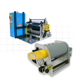
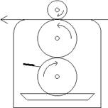
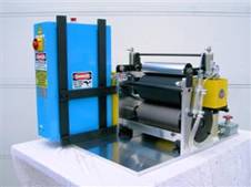
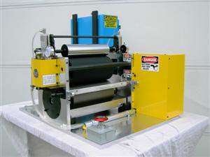
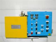
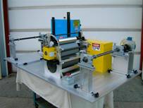
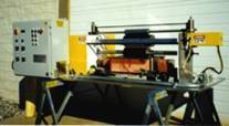
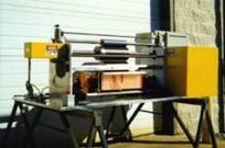
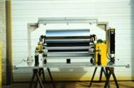
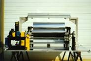
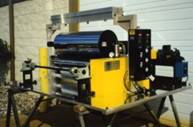
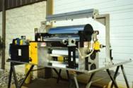
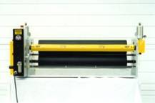
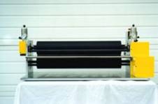
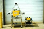
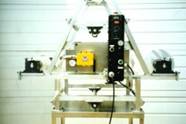
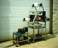
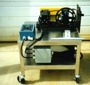
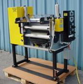
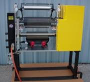
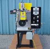
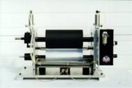
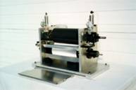
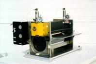
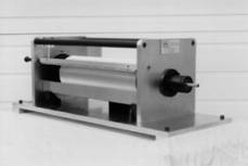
ผู้เชี่ยวชาญด้านการเคลือบผิวกระดาษสำหรับห้องปฏิบัติการงานเคลือบ หน่วยงานวิจัย ฝ่ายควบคุมคุณภาพ เป็นต้น มี3 แบบให้เลือก ได้แก่ เครื่องเคลือบแบบลูกกลิ้งเดี่ยว (Single Roll Lab Coater), เครื่องเคลือบแบบ 2 ลูกกลิ้ง (2 Roll Lab Coater) และ เครื่องเคลือบแบบ 3 ลูกกลิ้ง (3 Roll Lab Coater) นอกจากนี้ยังมีเครื่อง Laminator และเครื่องอื่น ๆ ที่ออกแบบตามความต้องการของลูกค้า ดูรายละเอียดเบื้องต้นด้านล่าง
| เครื่องเคลือบแบบลูกกลิ้งเดี่ยว SINGLE ROLL LAB COATER |
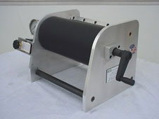
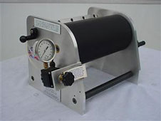
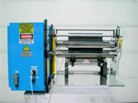
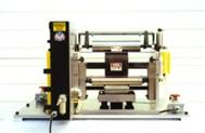
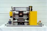
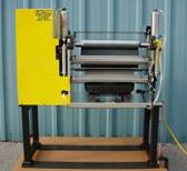
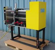
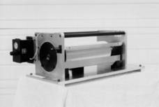
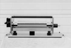
Single Roll Lab Coater, Manual Unit: Model#E-BC12M1
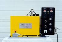
Single Roll Lab Coater, 110 Volt Power Unit: Model#E-BC12P1
Single Roll Lab Coater, 220 Volt Power Unit: Model#E-BC12P1
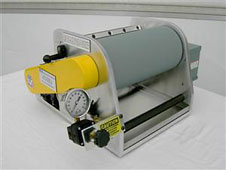
Optional: Precision Air Regulator and Air Gauge for extreme accuracy and precise control of pneumatic wiper blade for controlling final coating weight:
- Excellent for doing drawdowns and performing tests onto small samples and hand sheets.
- Applies a uniform, consistent, and repeatable coating laydown every time.
- Primarily used for applying thin coatings onto papers and films.
- Applies coatings from as low as 1/10 of 1 micron (.000004”) to as high as 5 mils (.005”).
- Coat weight is controlled by varying the air pressure of the patented pneumatic wiper blade which presses against the back of the rubber roll (requires compressed air of at least 60 p.s.i. supplied by customer).
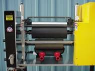
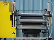
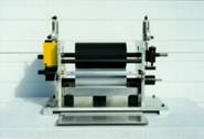
- Features a 6” diameter x 12” wide standard neoprene rubber roll, and mounts between aluminum side frames.
- Different types of rubber coverings for the roll including E.P.D.M., Silicone, Viton, Hypalon, Buna-N, Urethane, Polysulfide, and Natural Rubber are also available (prices vary).
- Manual unit contains a handle for rotating the roll.
- Power unit contains a variable speed motor and controller for rotating the roll, available in 110 or 220 Volts.
- Delivery time: 3 – 4 weeks
Instructions for use:
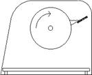
Simply attach one end of the substrate to the surface width of the roll by using a piece of tape, apply desired air pressure to the wiper blade, pour the coating mixture down between where the blade edge touches against the roll, turn the roll one revolution, and remove the coated substrate.
|
|
|
![]()
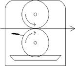
| เครื่องเคลือบแบบ 2 ลูกกลิ้ง 2-ROLL DIRECT GRAVURE LAB COATER |
|
Substrate |
 |
|
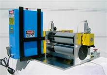
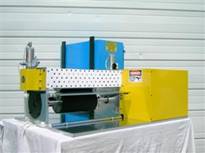
Direct Gravure Lab Coater, 12” wide: Model#E-BC12PDG2 – Direct Gravure Lab Coater, 18” wide: Model#E-BC12PDG2 – Direct Gravure Lab Coater, 24” wide: Model#E-BC12PDG2 – Optional: Special “Removable Top Roll” Feature for quick removal of Top Rubber Roll:
Instructions for use: |
|
|
|
![]()
| เครื่องเคลือบแบบ 3 ลูกกลิ้ง 3-ROLL OFFSET GRAVURE LAB COATER |
|
|
Substrate |
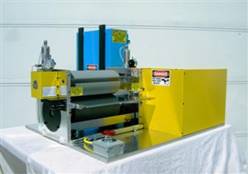
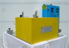
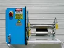
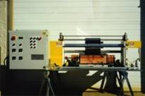
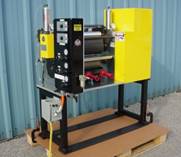
Offset Gravure Lab Coater, 12” wide: Model#E-BC12POG3 -Offset Gravure Lab Coater, 18” wide: Model#E-BC12POG3 -Offset Gravure Lab Coater, 24” wide: Model#E-BC12POG3 –
Optional: Special “Removable Center Roll” Feature for quick removal of Center Rubber Roll:
Optional: 2nd Emergency Stop Button mounted on opposite side base plate allowing easy access to E-stop buttons from either side of machine:
Instructions for use: |
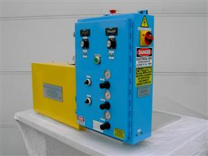 Click to Enlarge 3-roll Offset Gravure Lab Coater Side Panel View |
|
![]()
|
HOT MELT OPTION |
|
LAMINATORS |
|
UNWIND & REWIND OPTION |
| SPECIAL COATING MACHINES |
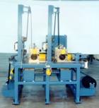
Euclid Coating Systems has the capability to design and build special, customized, and totally automated turn-key coating systems. With a complete staff of mechanical, electrical, and controls engineers, ECS can design and engineer special coating systems to meet the customer’s requirements.
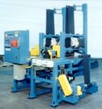 Special Two Station Direct Gravure Coating System |
|
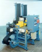 Special Two Station Direct Gravure Coating System |
|
Description of Special Two Station Direct Gravure Coating System:
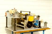
This machine contained air inflatable core lock unwind and rewind shafts, 3 web guiding systems and 3 tension sensor rolls for each of the 3 tension zones, and 2 separate coating stations. Coating station #1 applied a coating to the web using a “Direct Gravure” application, and coating station #2 saturated a top-coat into the web using two neoprene rubber squeeze rolls. The machine operated at 50 fpm maximum, and could be used for papers, films, non-woven materials, cloth, etc. The customer installed their own hot air ovens which dried the material after each of the coating stations.
|
|
|
|
|
|
Description of Special Heated Offset Gravure Lab Coater:
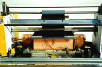
This unit contained an electrically internally heated center roll capable of 500 degrees F. The coating mixture resided in a heated stainless steel fountain complete with thermocouple providing constant read-out of the temperature that could likewise reach 500 degrees F. The bottom ceramic coated roll rotated in the heated fountain and picked up the coating mixture, and then passed by a doctor blade that helped meter excess coating from the bottom roll. The substrate could be fed either between the bottom and center ceramic coated rolls where it would receive the coating, or between the center and top ceramic coated rolls in order to be coated.
Both the top and center rolls were regulated with vertical air pressure in order to vary the amount of downward pressure. The center roll likewise contained a vertical height adjustment that allowed you to either set a gap between the bottom and center rolls, or to allow the center roll to make contact with the bottom roll. The entire unit operated with a 220 volt power supply and required a minimum air supply of 60 p.s.i.
|
|
|
|
|
|
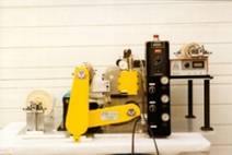
Description of Special 36″ wide Offset Gravure Lab Coater for Making Holograms:
This system had the bottom gravure roll and the center rubber roll driven together one-to-one with a serpentine belt and a variable speed motor and controller, capable of approximately 50 fpm, complete with a digital rpm tachometer. Both the top and center rolls were air regulated for applying downward pressure, and a vertical height adjustment allowed you to either set a gap between the bottom and center rolls, or allow the rolls to make complete contact. The bottom roll also contained an interchangeable feature that allowed you to utilize various gravure, rubber, or chrome rolls.
The system also contained a manual unwind unit, and a rewind unit that utilized a magnetic particle clutch for varying the tension on the rewind roll. The web unwound from the unwind unit and passed over the bottom gravure roll where it received the coating. The web then passed around the center roll and over the top chrome roll which contained a holographic image plate, and then exited off and onto the rewind unit. A U.V. curing bulb was mounted above the top chrome roll in order to cure the web as it passed over the top roll. The unit operated with a 110 Volt power supply and a minimum air supply of 60 p.s.i.
|
|
|
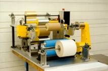
Description of 36” wide Direct Transfer Lab Coater/Lamination Machine:
The top and bottom rolls were driven together one-to-one with a serpentine belt and a variable speed motor and controller. The top roll was air regulated for applying downward pressure, and a vertical height adjustment allowed you to either set a gap between the rolls for various thicknesses of substrates, or allowed the rolls to make complete contact. The bottom roll was also interchangeable to allow for various types of rubber or chrome rolls.
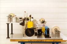
This machine also utilized a Halogen Sealed Beam Infra-Red bulb (inside the yellow guard) which projected an infrared ray onto the top roll in order to heat it. A Model LX25 Power Control was used to vary the output of the infrared bulb allowing accurate control of the temperature of the roll up to @ 300 degrees F.
|
|
|
|
|
|
Description of Special 3 Ply Lamination Machine:
This is a 13” wide unit that was built for a Medical facility that was actually bonding 3 separate laminates together. This unit had the two EPDM rubber rolls driven together one-to-one with a serpentine belt and a variable speed controller.
The two rolls were horizontally displaced, and one of the rolls had a horizontal adjustment in order to set a specific gap between the two rolls or to close the rolls together completely. Dial indicator read-outs located on each side of the roll allowed you to determine the exact amount of adjustment that was made to each side of the roll. The adjustable roll was also air regulated in order to vary the amount of pressure that was applied against the other roll.
Two adjustable dams (one on each side) were positioned on top of the two rolls and could be positioned horizontally along the width of the rolls. This helped prevent the coating from spilling over the edges of the rolls and also allowed for various widths of material to be used.
All of the unwind units had steel shafts with aluminum plugs which held the 3” diameter cores, and also contained set collars on the steel shafts for holding the rolls of material in place. On each side there were two shaft support holders that held the steel shafts in place. The shafts were mounted on these shaft support holders, and allowed for easy changing of the rolls. The shafts were removed by simply loosening the two shaft support holders, pivoting the holders upward, and then removing the steel shafts.
|
|
|
|
|
|
|
|
|
|
|
|
Special 18″ wide Offset Gravure Lab Coater |
|
|
|
|
|
|
|
|
|
|
|
|
|
|
|
|
|
|
|
|
|
Description of Special 6” wide Offset Gravure Lab Coater:
The paper unwound from a manual unwind stand and then wrapped around two web cleaning rolls which removed all excess debris from the paper. The web then proceeded directly into the coating station where it received an adhesive coating by direct gravure application. After the paper received the adhesive, it then wrapped around the center roll, and a second unwind stand unwound a foil which was laminated to the paper as the two substrates met at the nip point between the center and top rolls. The laminate was then wound onto a rewind stand. Subsequently, the customer also had a web guide unit installed between the two web cleaning rolls and the coating station in order to control the lateral flow of the paper as it entered the coating station.
This system also had the bottom gravure roll driven by a variable speed motor and controller, capable of approximately 50 fpm, complete with a digital rpm tachometer. Both the top and center rolls were not driven, but were both air regulated for applying downward pressure, and a vertical height adjustment allowed you to either set a gap between the bottom and center rolls, or allow the rolls to make complete contact. The bottom roll also contained an interchangeable feature that allowed you to utilize various gravure, rubber, or chrome rolls.
|
|
|
Description of 36” wide Stand-alone Unwind Unit:
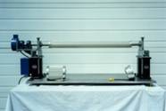
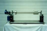
This stand-alone unwind station consisted of an aluminum base plate which supported the entire framework assembly. Located on each side of the aluminum base plate were two mounting stands that supported the shaft holders which held the air expandable unwind shaft. A simple clamping mechanism allowed for easy releasing in order to have immediate access to the air expandable unwind shaft.
The air shaft ensured positive locking without core damage and was virtually maintenance free. The air shaft tube was inflated by simply pressing an air gun to the air stem and squeezing the gun, thereby allowing air into the tube immediately. Once the tube was inflated, it provided uniform and controlled expansion for the aluminum leaves and full surface engagement with the core I.D., allowing it to lock securely to the shaft. A simple press on the center of the air stem deflated the air shaft immediately (much like a bike tire). The air shaft could accommodate a 3” diameter core, and by simply adding a 6” diameter end plug to each end would allow for a 6” diameter core.
The unwind unit also contained a Magnetic Particle Brake which varied in tension in order to accommodate for the continual changing diameter of the unwind roll. This braking mechanism fastened to one of the mounting stands and connected by means of a coupler to one end of the air shaft. A tension controller was also mounted to the assembly and controlled the desired amount of tension on the web by simply turning the control knob.

